
| Introduction |
|
| The Jig | |
| Saw Setting | |
| Saw Filing | |
| Some Theoretical Issues | |
| Sloping Gullets | |
| Copyright (c) 2002-15, Brent Beach |
Today, most saws are filed with the base of the gullet square to the plane of the saw plate. When I first started filing saws, that was how saws were filed. No question.
One day in '96 (?) a galoot named Steve LaMantia (yep, the same guy who coined the phrase scary sharp) posting on the old tools list asked if the drawings in the Disston Lumberman's Handbook 1919 could be taken to suggest that, in the past, people filed so that the base of the gullet sloped. See Figures 10, 11, 12 on pages 158, 159. Notice the shadow of the file on the saw plate. People on the list looked at the pictures, but could not come to any conclusion - was it just the artist trying to represent 3 dimensions in two? Around this time the term sloping gullet was first quoted, from the writings of Harold Payson.
In his 1996 book, Leonard Lee mentions sloping the gullet as the way to keep the gullet angle around 60 degrees. The problem he is addressing, as you will see below, is that as you increase the bevel angle you also increase the gullet angle and shorten the teeth. In one place he says: "drop the handle the same number of degrees as the amount of bevel you are using" implying that will get you a 60 degree gullet angle (it won't). In another, he writes: "In practical terms, this is not worth the effort." I think he is saying there is no need to worry that the bevel and gullet angles are idential - just do what works. He does not mention sloping the saw plate during filing and his saw vises are shop made and do have slope adjustments.
Over the years, occasional investigation each time the idea came up produced the material in this page. Not a lot of time spent in total - an idea here, an idea there. Some time figuring out how to make a saw using Sketchup. An interesting occasional hobby for me.
From a relatively obscure idea that had been lost with the increased mechanization of the saw filing trades, sloping gullets are now main stream among people who prepare saws for sale on eBay. There are several who file most cross cut saws they sell this way. How much more main stream can you get than eBay?
I hope they clarify many of the issues related to sloping gullets and to saw filing in general. Let me know if you have any quesitons about any of the drawings.
 If you read most descriptions of how to sharpen saws written since 1920, you would know to place the saw in a saw vice with the teeth vertical, then file with the file horizontal. This drawing is from the 1926 Disston booklet on saw filing.
 Disston saw filing advice in 1875 was quite different. This 1875 drawing clearly shows a saw vice that was designed to tilt. The joint allowed you to angle the saw plate from the vertical. You then worked with the file horizontal.
 This drawing is from the Disston 1876 Catalog. To me it looks much more modern than any saw vice produce at the time, or for many years after. I have not seen any other reference to this saw vice, no patent, no pictures. If you have a source for more information of this saw vice, please send it along and I will add to this page.
The advertising copy reads:
|
This engraving represents our new Clamp, with hand saw in position for filing. Experience has demonstrated that a fast-cutting cross-cut saw must have deep teeth. To make them deep they must be filed on an angle. To do this to advantage, the Clamp should be set to the desired angle, as shown in cut, and the deep gullet tooth can, by this means, be filed even more readily than the square bottom tooth. Another great advantage to be derived from this mode of filing is that the teeth can be set more easily and with considerably less risk of breaking. A cord attached to lever at B, and operated by the foot on treadle below, is used for screwing up the Clamp, thus leaving both hands free to guide the saw.
We are now making a first-class saw with this style tooth. It should be filed and kept in the same order in which it leaves the factory. This ean be readily done by using the above Clamp, and following directions. The Clamp can be set to any desired angle, or used square, as shown by dotted lines. It is gotten up in first-rate and durable style, and weighs twenty pounds. Be sure to clean the saw teeth before filing, and use the Little Wonder File. |
In 1876, Disston was manufacturing saw vises designed to allow sloping gullets because saws filed in this way were faster cutting. By 1926, Disston had stopped mentioning these both saw vises and sloping gullets.
How did something that was common knowledge in the late 1800's disappear from the literature without a trace?
Why did they slope the saw when filing back then? Why did they stop?
 This patent took a different tack - it provided a platform you could adjust to provide the desired gullet slope. The late date of this patent shows that sloping gullets were still being considered as the century closed.
The typical advice back then (when these old Disston booklets were in wide distribution) was to provide such a drawing and then tell the woodworker to file the teeth to look like the drawing. That was it - when you are done the teeth should look like this. No mention of technique at all.
This page is an exploration of the issues involved. I began with some drawings in the Disston Lumberman's Handbook - 1916 or so. Others thought that these drawings might have been to scale and indicated practical teeth filings. Sadly, after considerable time spent scanning, enlarging, and counting pixels in these diagrams, I have concluded that they can show us nothing about tooth shapes - they are simply not accurate drawings.
I then spent some time rediscovering high school geometry and worked out the geometric rules that govern tooth shape. For any combination of the angles involved, these formulae define the tooth shape. I have included a number of drawings of tooth shapes and will add more as time goes on. For each combination of angles I have included face and front profiles.
I am interested in input on any part of these web pages. My contact information is at the bottom.
Why does it matter
Before spending a lot of time on sloping gullets, we have to understand why we would bother.
The following three Sketchup models of teeth with different filings show the issues involved.


| Rake - the angle between the file face and the vertical, in the plane of the saw plate. I removed parts of the jig to make this angle visible. | 
|
| Bevel - the angle between the file axis and the perpendicular to the saw plate, in the horizontal plane (when the saw is vertical). | 
|
| Slope - the angle between the file axis and the saw plate, in the vertical plane perpendicular to the saw plate. | 
|
|
As we shall see later on, defining these three angles in terms of the orientation of the file could be confusing. For example, depending on exactly how you set the rake, bevel, and slope, the rake as measured on the tooth need not equal the rake as measured on the file producing the tooth.
This astonishing result goes unmentioned in the descriptions of saw filing. |
The slope is defined as the angle the file handle drops down from the horizontal.
You could file this way, by dropping the file handle by the slope angle. There is a second way of getting a sloping gullet - you can tilt the saw and keep the file horizontal. Most metal saw vices have the ability to tilt to allow for sloping gullets. Here is an illustration from the Disston Price-List 1876 (Roger Smith reprint 1994).
This is the explanation that appears in the 1888 Disston Lumberman's Handbook (referring to the drawing on the right):
| A fast cutting cross-cut saw should have deep teeth. To make them deep they must be filed on an angle; to do this to advantage the clamp (see engraving) should be used, and thus a deep gullet tooth can be filed as readily as a square bottom tooth. |
This illustration shows a fairly large bevel and slope angle - perhaps 30 degrees or more. It also makes it clear that filing with non-zero slope was standard practice back in the 1870s. Why is it not done, not even known today?
Unlike the saw vice in this drawing, some saw vice designs only permit a tilt in one direction - away from the filer. These vices clamp to the bench top with a screw from below. Part of the vice is below the bench top. This part collides with the clamp part, preventing tilt back toward the filer. This means you can only file up the gullet, not down the gullet. Since the down part of the gullet is always pointing back toward the handle, this means the file handle must always point back toward the handle during filing with sloping gullets (using these saw vices).
I have figured out how to use Google Sketchup to make scale models of saws, based on the rake, bevel, and slope used when filing the saw.
My Sketchup models of hand saws page explains more about the model - what type of saws are modelled, what files are used, what the various measurements of the resulting saw teeth are.
You should read this page if you have any questions about the Sketchup models here.
The Sketchup models accurately reflect the saw tooth shape for the specified rake, bevel and slope angles if you use my jig. In all cases, both sides of the file are in contact with the teeth on either side of the gullet.
I have scanned these pictures, then enlarged them in a graphics program and counted pixels to determine original sizes of teeth, and various angles.
It turns out, unfortunately, that the drawings are not to scale. Pixel counting in enlargements of the drawings produce front and back rake angles that are inconsistent with the stated bevel angles. Some drawings show sloping gullets - the gullet bases alternate up and down - but there is no mention of sloping gullets in the text. Some drawings show teeth profiles that can only be achieved with sloping gullets, but the drawings do not show sloping gullets.
I suspect that by 1918, when this revision of the original 1907 Handbook was published, sloping gullets had gone out of fashion. Some references were edited out, others did not get removed. The result is confusing and misleading.
I have retained the material here for others interested in historical saw tooth drawings.
This book contains the earliest drawings of saw teeth I have encountered. It appears to be the model for most subsequent books, including the Disston Lumberman's Catalog.
 This is Holly's drawing of a cross-cut saw for use on soft woods. Holly never mentions angles in his book - he shows a picture and tells people to file their saws to look like the picture! If people had no access to small protractors or other ways of measuring angles, this probably makes sense.
The front and back bevels appear to the be same, and the gullets line up. The front rake is 19 degrees, the back rake 51 degrees, included angle 70 degrees.
 This is Holly's drawing of a cross-cut saw for medium wood. The only difference in saws for soft and medium woods appears to be in the number of teeth per inch -- he recommends 6 teeth for soft woods, 8 teeth per inch for medium woods. The gullet bottoms again lie on a straight line.
The front rake is 27 degrees, the back 48 degrees, included angle 75 degrees.
 This is Holly's drawing of a cross-cut saw for hard wood. Again he changes teeth per inch - now recommending 10 teeth per inch. The front rake is 25 degrees, the back 43 degrees, included angle 68 degrees.
The big difference now is that he recommends that "the back of the tooth be filed square".
He also says that a saw filed this way "will mitre soft or medium wood well".
The gullet bottoms are no longer on a straight line. This filing is achieved, in part, by sloping the gullet. Holly gives no indication of this - he says nothing about gullets in relation to hand saws. Was the technique so well known that it need not be mentioned?
 This is Holly's recommendation for a back saw for use on soft woods - 10 teeth per inch. The front rake is 25 degrees, the back 39 degrees, included angle 64 degrees.
He says it has the same bevel as figure 12. It sure does not look like it to me - the teeth look taller.
This saw has quite a pronounced bevel. As the number of teeth increase, the size of the tooth gets very small if you file the teeth with no slope and large bevel. Usually the teeth look quite squat. These teeth look quite tall. It could well be that Holly meant people to use a slope when filing these teeth. However, if that is so then the drawing should show zig zag gullet bottoms.
 This is Holly's drawing of a back saw filed for use with hard woods - 12 teeth per inch. The front rake is 25 degrees, the back 36 degrees, included angle 61 degrees.
Again, he recommends that the tooth back be filed square. Again, the gullet bottoms zig zag.
A mitre saw - a saw used in a mitre box - is a back saw. Mitre saws are often filed as peg teeth - same filing on the front and back of the tooth so they can cut in both directions. A saw filed square on the back would not present the same knife shape on the back stroke. I wonder if this matters.
You may be confused by these drawings. They seem to be less than clear to me. No angles involved. No explanation of why things are done this way. Just a few drawings that are easily misunderstood.Were individual workmen sharpening their own saws back then? Were they sending them out to shops that jealously guarded the secrets of their craft? Were the actual techniques passed on from filer to filer as part of the apprenticeship experience?
| "Now the sharper each tooth is -- that is the more bevel on the point -- the deeper it will cut; but it must not cut any deeper than will crumble out across to the point of the other tooth. This is the difference between saws for soft or hard wood; if a saw for hard wood is too much bevel on the point, it will score deeper into the wood than it can carry out the chip, so that it will keep moving up and down in the same scores, and not accomplish anything." |
Sloping the file, and hence sloping the gullet, is the only way to achieve the latter two filings in figs. 14 and 16 above if you use triangular files.
 Soft Wood
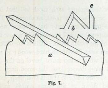
From Holly:
|
a shows the position of the file for a cross-cut saw for soft wood, such as pine, bass wood, cedar, etc.
b Shows the shape of the tooth, and c the bevel of the point, consequent on the position of the file and bevel of the back of the tooth. |
Looking at b: the front bevel is wider than the back bevel. You cannot achieve this filing if the file is in contact with both teeth at the same time. You can do it by adding a little slope, which allows you to file the fronts on one pass and the backs on a second pass. This should be clear in the drawing - the gullet bottoms should zigzag, but they do not.
Looking at c: [the way the wood sees the tooth] the tooth is tapered sharply to the tip. The tip will slice deeply into the wood. When used with soft wood the chips will be easily pushed sideways by the alternating teeth, break off, and be carried away in the gullet.
 Medium Wood
From Holly:
|
a shows the position of the file for saws for medium wood, such as chestnut, bay-wood, black walnut, cherry, etc.;
b shows the shape of the tooth, and c the bevel of the point. |
Looking at b: the bevel on the back of the tooth is about half as wide as the bevel on the front.
Looking at c: the front profile is not as sharply pointed.
Comparing Figs 7 and 8, it appears in Fig 8 that the slope of the file is larger. He is using sloping gullets, so the gullet bottoms should zigzag, but again they do not.
 Hard Wood
From Holly:
|
a shows the position of the file for saws for hard wood, such as hickory, ash, oak, maple, beech, etc.;
b shows the shape of the tooth, and c the bevel of the point. |
Looking at b: the back of the tooth now as no bevel.
Looking at c: the tip is quite blunt.
Again, comparing these last 3 Figs, the file appears to have more slope in Figs 8 and 9 than in Fig 7. In this drawing the zigzag of the gullet bottoms is quite clear.
According to Holly, this flatter front profile means that the chip is broken off by the action of successive teeth. With hard woods you need a fairly blunt front profile or the tip goes so deep that there is so large a chip that it does not break off.
 Fleam-Tooth Filing
A distraction possibly, but included because I cannot understand the drawing.
Holly calls this a Fleam-Tooth Saw. He says: "This saw is filed extremely beveling, so much so, that the saw must be laid down flat to be filed." Notice as well that this is the only case in which you file down the gullet. If you did this filing up the gullet your hand or the file handle would hit the saw spine.
It appears that the slope is almost 90 degrees. This is the most extreme case of sloped gullets. Holly does not say where you would use a fleam-toothed saw.
 I bought this saw - a Disston 112 - at auction at the Whippletree Auction north of Victoria, in April 2005, with 3 other saws. All three saws looked fairly well sharpened.
I tried this saw out but found that it cut very poorly. It worked, but slowly.
The image is magnified 10 times.
The lower red line is the line of the bottoms of one set of gullets, the upper red line shows the bottoms of the other set of gullets.
This zig zag gullet bottoms is a sure sign of sloping gullets.
Looking closely at the teeth set away, the front face of the tooth appears to have bevel 0 while the back of the tooth has bevel around 15 degrees. The rake appears to be around 15 degrees, perhaps a little more.
The problem with this saw is that in filing the gullets, the filer hit the fronts of half of the teeth with the file -- blunting half the teeth. I don't think a hand filer would make this mistake and not notice. I suspect this saw was machine filed using a bad setup in an attempt to achieve a complex filing without using any slope.
 This is a 2400 dpi image (600 dpi scan, 4x digital zoom) of an relatively modern Atkins Silver Steel (the stamp included the words Borg Warner) mitre box saw (no model number in the stamped makers mark), with the teeth almost vertical to the scanner.
You can see there is almost no set on this blade - this high resolution scan shows a little set, I thought there was none after a close visual inspection. It looks in this scan like the tooth shape switches from tooth to tooth - the set up for filing one set of teeth differed from that for the other set of teeth. This means that the saw will pull to one side, moving to the side with the sharper teeth.
The high resolution scan also shows the file marks on the back of the teeth. This is not visible to the naked eye. Does saw filing always leave file marks like this? Should a finer file be used to go over the saw, perhaps a triangular abrasive file (Silicon Carbide, Aluminum Oxide). Do they even make abrasive files with the corners rounded like saw file corners are rounded?
The saw is 10 tpi, 11 ppi. The saw plate is 0.038" thick. It is 22 1/2" along the teeth and 4" below the spine.
 This is a 1200 dpi scan of the same saw. These teeth have the most extreme sloping gullets I have seen on a saw. The front of each tooth is highly beveled, while the back has almost no bevel. A very unusual filing.
The teeth fronts look almost as if the file had a slightly rounded surface, almost like the teeth are slightly hooked. The teeth look more like rip teeth than cross cut teeth. A mitre box saw can be expected to do mostly cross cuts.
The teeth backs have a rake of 60 degrees (angle from the vertical).
The gullet base is also 60 degrees from the vertical: the slope and the bevel are equal.


 This Disston Acme 120 appears to have an original filing. After all this time of course, that can only be speculation. In any case, I balanced a needle in a gullet to determine the various angles involved. The saw has 11 ppi.
Viewed from above, the bevel angle is about 40 degrees.
The side view shows the teeth clearly. The teeth have very small front and back rake. The rake angle for teeth facing left is about 24 degrees, for those facing right about 18 degrees. Notice as well, the tips are dull! I have left this saw as found - retaining the filing. The tooth height (tip to lower gullet) is almost the same as the tooth width 0.1".
The front view, taken from the toe looking along the teeth to the needle, shows a slope of around 20 degrees. The saw may be tipped a little to the right.
 This is the sketchup model for the angles that appear to have been used for the ACME 120 above. This is what you would get if you used my jig and rake 24, bevel 40, slope 20.
As explained in the Sketchup saw models page, using my jig implies an certain order and method in orienting the file to the saw. The bevel angle comes from the angle of the hole through the slider. The rake angle comes from turning the file so the face rests against a block of wood with the desired rake angle. The slope comes from the angle of the kerf in the slider base.
Even though the bevel angle is correct in the slider, using an angled kerf to get the slope has resulted in a different bevel angle on the tooth.
 Using a jig in which the rake is 24, the bevel is 40, and the slope is 20 has resulted in teeth:
 This is the sketchup model you would get if you used my jig and rake 24, bevel 32, slope 20. Reducing the angle of the back dowel hole in the slider results in a tooth shape closer to the Acme pictured above. It took some experimentation to find that an 8 degree change in the bevel angle in the slider produced an almost 7 degree change in the angle on the tooth. Perhaps a slider with a 32.6 degree bevel angle would produce the 40 degree bevel angle on the tooth.
Using a jig in which the rake is 24, the bevel is 32, and the slope is 20 has resulted in teeth:
This is the sketchup model you would get if you used my jig and rake 24, bevel 32, slope 20. Reducing the angle of the back dowel hole in the slider results in a tooth shape closer to the Acme pictured above. It took some experimentation to find that an 8 degree change in the bevel angle in the slider produced an almost 7 degree change in the angle on the tooth. Perhaps a slider with a 32.6 degree bevel angle would produce the 40 degree bevel angle on the tooth.
Using a jig in which the rake is 24, the bevel is 32, and the slope is 20 has resulted in teeth:

 One more filing near the observed. This one has rake 25, bevel 25, slope 25.
Again, a slightly taller tooth with a slightly larger front included angle. Perhaps a good filing for hardwoods (better than other models).


 The teeth in a filing with rake 30, bevel 30, slope 0

 The teeth in a filing with rake 30, bevel 30, slope 10

 The teeth in a filing with rake 30, bevel 30, slope 20

 The teeth in a filing with rake 30, bevel 30, slope 30
Tooth height, gullet volume and front included angle are the three key factors in the tooth shape. Summarizing the key measurements from these four models:
| Slope | Height | Volume | Front Included Angle | ||||||||||||
|---|---|---|---|---|---|---|---|---|---|---|---|---|---|---|---|
| 0 | 0.066" | 210 | 49.2 | ||||||||||||
| 10 | 0.084" | 215 | 48.9 | ||||||||||||
| 20 | 0.092" | 225 | 46.9 | ||||||||||||
| 30 | 0.102" | 243 | 43.0 |
Think instead of a filing in which you first tilt the saw blade away from you at the desired slope - as in the drawings from the old Disston Saw Manual. You work with the file horizontal and turn for the bevel in the horizontal plane. Finally, you rotate the file for the rake again using something like a slider on the teeth to get the rake.
This filing is slope, bevel, rake or SBR. The angles are: slope 30, bevel 30, rake 30.
Notice that even though the saw plate is tilted as 30 degrees, the slope of the gullet is greater than 30 degrees.


Not greatly different from the results from the BSR filing.

 First, the basic rip filing: rake 5, bevel 5, slope 0.

 Second, a rip filing with slope: rake 5, bevel 5, slope 20.
This filing would be produced from my jig with a 5 degree bevel angle and a 20 degree slope angle (to the saw kerfs), with the rake set from a slider with a 5 degree front angle.
Adding the slope has not slightly changed the sharpness of the tooth with a very small increase in the front bevel angle.
The next set of models attempt to discover file positions that produce the tooth shapes that appeared in Holly's book. It is clear from the models above that he did not use my jig! Since the SBR filing is so much like the BSR filing, it appears he did not use that either. What did he do?
If you discover a file orientation that produces a Holly filing in one pass, please send me an email with the details.
It looks like the file has lots of rake and slope, but no bevel.

 I am not sure if this saw would even cut wood! In the front view, the teeth do not look like the tops are square to the side, but they are. The apparent tilt is a result of the perspective only.


A strange result. In all models the front of the tooth is on the left. This filing might produce a fast cutting crosscut if the front of the tooth is on the right - that is, a pull saw. That is, use this filing on your push saw then use it as a pull saw. I have not tried this. Changing the filing of a saw is a laborious process which usually begins with removing the existing teeth. If you do try this filing, I would like to hear if it worked at all.