|
| Bevels - New and Used |
|
| Finest abrasives. | ||
| Microbevels front and back. | ||
| Use a jig. | ||
| Copyright (c) 2002-15, Brent Beach |
For most people, a cutting edge -- say a knife -- has two bevels. When first thinking about a plane blade, most people think it has only 1 bevel - forgetting that the back of the blade is also a bevel. As I spent more time looking at worn plane blades under the microscope, I came to the conclusion that the sharpest edge can only be produced using a series of abrasives, each producing its own bevel, on both the front and back of the blade. This pages discusses the issues involved.
Drawings in this page for the most part show plane blades in the position in which they are used - the blade is angled at 45 degrees. The upward face deflects the shaving, the downward face presses down on the work.
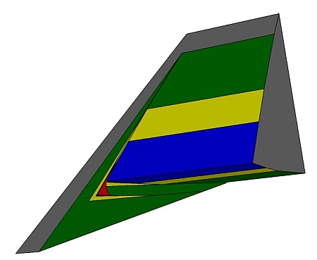
Because the effects of interest all take place within the last 0.01" of the blade, the drawings show only the last 0.02". Most of the new drawings were made in Sketchup. In these drawings the unhoned parts of the blade are shown in grey, the first microbevel in green, the second microbevel in yellow, the third microbevel in blue, and the wear bevel in red.
These models were drawn to show the blade as it sits in the plane - 45 degree bedding angle. However, in order to show both front and back bevels I had to move the point of view around a little. So, the front of the blade faces down, the back of the blade faces up. [The bevel up case is covered in detail later.]
This page contains several Sketchup models. Are these models confusing? Check out the introduction to Sketchup models that shows honed microbevels and wear bevels.
After some use you end up with a dull blade. This model shows both the sharp and dull shapes. The left third of the blade shows the original bevels - in grey. The right two-thirds shows the wear bevels - in red. Notice that the upper wear bevel is much longer than the lower wear bevel.
The transition from the sharp shape to the worn shape is gradual, with the wear increasing slowly when the blade is sharp, more quickly as the blade becomes duller.
The important point is that the back of the blade is no longer flat. In the region near the edge, the back of the blade is very slightly sloped. The amount the back is out of flat is shown by the grey along the red in the tab at the left corner.
Think for a moment about your current sharpening method. Does your sharpening method do anything to this narrow wear bevel on the back face? The next section looks at the range of possible ways any sharpening method can produce a honed back face at the edge.
Strategy 1, return the blade to its original condition. This means that the sharpening method produces a flat back. The entire back, from end to end, is flat.
Strategy 2, use back bevels. This strategy accepts that there will be a small band near the edge that is not in the same plane as the rest of the back. It also ensures that this small band is flat and smooth.
Unfortunately, this approach involves removing a lot of metal. You would be removing about 0.005" thickness from the back of the whole iron. When an iron begins at only 0.1" thick, this is a problem, even if you could do it.
This is the more likely option - what most people are apt to do. First, they sharpen the front bevel back through the worn edge until they have ground off most of the back wear. Second, they flatten the back.
Notice that this method must involve grinding - no pure honing method can remove this much metal.
Most people who use this approach - sharpening only from the front - think their sharpening method is achieving this result. It probably is not. Most people will not remove as much metal as shown by the lower line. Once the wear bevel, as viewed from the bevel side, disappears, most people will stop. You can see from these drawings that stopping too soon leaves a rounded portion of wear bevel on the back of the iron. In fact, they think they are following option 2 but they are really following option 1.
If you go as far as the line shown in this drawing you will have removed most of that rounding. People who grind until they "raise a good burr" are following this approach.
Some flip the blade and hone a bit on the back with the blade flat on the abrasive. The back wear bevel is not in the plane of the back. It is off the abrasive and is not getting honed. No one hones long enough to remove the back wear bevel by honing with the blade flat on the abrasive. Some use leather strops. The leather will deform and follow the shape of the wear bevel. The result is an increase in rounding, not a decrease. Any sharpening operation on a yielding surface will produce an edge effect - a rounding at the edge.
So, most people will not get a sharp edge - they won't remove enough metal. Those that do get a sharp edge - achieve the desired geometry - by grinding away enough metal from the front, will also have a weak edge.
Why is the edge weak? The reasons for this are complex. In summary, grinding using coarse abrasives not only produces a deeper damaged layer at the surface (deeper scratches) but also produces a deeper layer of significant deformation. The metal in this second layer has had its crystal structure shattered. The depth of the layer of significant deformation is up to 15 times the depth of the surface scratches. The metal in this layer wears quickly. The result is a sharp (has the correct geometry) but not a durable edge. [More on the properties of abraded metals coming soon in a new page on Metallography.]
Also called the "denial is a river in Egypt" method.
Any sharpening method that includes an operation that flattens the back is in denial. Other phrases used instead of flatten the back include give the back a couple of swipes on the fine stone and strop the back on leather using a stropping compound. No such method can work because flattening the back requires the removal of too much metal. Any sharpness improvement can only occur if the method is actually producing an angled back near the edge.
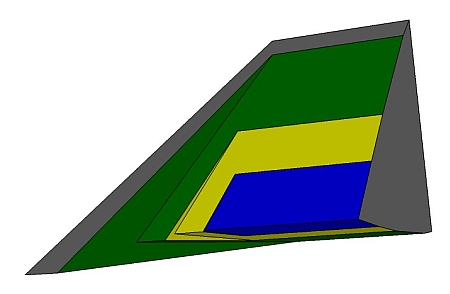
In this model, I show four different bevel combinations. The model represents the last 0.04" of the blade. Remember, the lower face is the front bevel, the upper face is the back bevel.
This quarter shows the final shape of the blade.
Can Strategy 2 really be easier than Strategy 1? It looks pretty complicated, with very narrow bevels.
It turns out that you can create this complex shape quickly and easily. It has the advantage of completely removing all the wear each time you hone. You get fast, consistent sharp tools. See Sharpening with back bevels.
With that introduction to the sharpening problem, time for a review of the terminology.
New blade gets dull
 The back of a new plane blade is more or less flat - it may be a little rough and have a few machining marks, but it is pretty flat. The bevel is also pretty flat. In some case, like recent Lee Valley blades, the back is very flat. You can hone the front (at the original angle or use microbevels) and use the blade. It will work pretty well.
Possible strategies
Any sharpening strategy must try for one of two outcomes.
Strategy 1, option 1
Strategy 1 - flatten the back. Option 1 - aim for the middle of the wear bevels.
 The first option is to remove about as much metal from both sides of the blade, ending up with a new edge in the middle of the worn edge. In this model, the left third is the original blade shape, the middle third is the worn blade shape, the right third is the new blade shape.
Strategy 1, option 2
 Strategy 1 - flatten the back. Option 2 - remove most of the back wear by grinding from the front.
Strategy 1, option 3
Strategy 1 - flatten the back. Option 3 - ignore the problem.
Strategy 2 - Sharpening using Back Bevels
 Rather than try to get back to the original condition - where the blade back is flat - a second strategy is to create a new sharp condition - one using microbevels on the front and back.
Bevel naming conventions.
When you first look at a plane iron, you see only one bevel. When there is only one bevel, it is ok to simply call it the bevel (or Bezel!). When there are lots of bevels we have to be more careful, adding qualifiers to identify each bevel clearly. So, excuse the heavy lifting of making of a lot of names for bevels - it will avoid problems later on.
Primary BevelThe big bevel that everyone sees -- that is there when you buy a new iron -- is the main or primary bevel. Manufacturers usually recommend a primary bevel angle of about 25 degrees.The face of the iron that has the primary bevel is the FRONT of the iron; the other face is the BACK of the iron. (This is an arbitrary naming convention. Others use exactly the opposite terms.) Bevels on the front of the iron are also called front bevels, while bevels on the back are called back bevels. MicrobevelsGrinding is the process that creates the primary bevel. Once we have ground the primary bevel, we hone microbevels. We create these microbevels by very slightly increasing the honing angle and honing on a finer abrasive. At each step we remove the scratches left by the earlier grit, while putting on new finer scratches.I use three abrasives - 15, 5, and 0.5 micron - to put three microbevels at ever increasing angles. The result is an edge that has been honed on both sides using an extremely fine abrasive. What is more, the process has removed all of the scratches from earlier grits in the region at the edge where all contact with the wood takes place. Microbevels as a sharpening technique have been around for a long time. In fact, the very first issue of Fine Woodworking January 1976 included an article by Bruce Hoadley "Micro bevels; getting a better edge." This article is available on the Fine Woodworking website. [Note: The article is wrong in asserting that the microbevel does not affect chip formation. In fact, all contact between the wood and the blade takes place on the front and back microbevels.] Leonard Lee also mentions micro bevels in his 1996 book. Wear BevelsThese microbevels are all good bevels produced during sharpening. The bad bevels, the wear bevels, are produced during use.If you have never seen pictures taken by the QX3 microscope, you should read the short introduction to the QX3 microscope and the pictures it takes. That article includes some images of razor blades. Most microscope pictures of cutting edges show just the sharpened edge. I am going to show you sharpened and worn edges. This discussion is based on using bevel down planes - normal bench planes. That means that the front bevel faces down toward the work during use, while the back bevel faces forward toward the shaving. |
|
|
This is a freshly sharpened blade, front side, showing the 4 bevels, with the edge at the top.
The third microbevel, labelled 32 degrees and produced using 0.5 micron abrasive, is the dark area at the edge. This area looks like it is scratch free because the scratches left by the 0.5 micron abrasive are too narrow to reflect light. I am still looking for an electron microscope to get an image of these scratches. This microbevel is about 0.0045" wide. The second microbevel, labelled 31 degrees and produced using 5 micron abrasive, has fine scratches going up to the left. Of course, immediately after honing this microbevel these scratches went right to the edge and this microbevel was about 0.01" wide. The last honing step removes the part of the second microbevel at the edge, while producing the third microbevel. The first microbevel, labelled 29 degrees and produced using 15 micron abrasive, has deeper scratches going up to the right. Immediately after honing this microbevel, these scratches went right to the edge and this microbevel was about 0.025" wide (under 1/32"). The primary bevel, labelled 25 degrees with rough scratches going up to the left, is at the bottom of this picture. I usually grind the primary bevel using a coarse Silicon Carbide bench stone. |

|
|
This is an image of the microbevels on the back of a freshly sharpened blade.
The area labelled 3 is the third microbevel, produced using 0.5 micron abrasive. For a typical blade this microbevel is at an angle of around 4.3 degrees to the back. The area labelled 2, with scratches slightly angled up to the right, is the second microbevel, produced using 5 micron abrasive. For a typical blade this microbevel is at an angle of around 3.4 degrees. The area labelled 1, with near vertical scratches, is the first microbevel, produced using 15 micron abrasive. For a typical blade, this microbevel is at an angle of around 2.4 degrees to the back. |

|
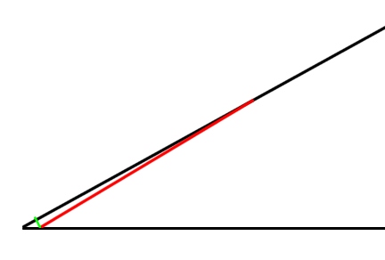
 Using the dimensions from the above images, this is a scale drawing of the primary bevel - in black - with the first microbevel shown in green.
You will notice that the first microbevel has honed a very small portion of the primary bevel. The primary bevel is 0.22" wide, the microbevel only 0.025" wide. The depth of metal removed at the edge is calculated to be 0.00174".
To remove that much metal over the entire primary bevel would mean removing almost 16 times as much metal. That is, it would take 16 times as long and wear out 16 times as much abrasive.
 This is a scale drawing (equivalent to about 300 times magnification), of the tip of a plane blade - the 0.01" at the tip. The blade is drawn as if it was back down, edge facing left with the front side microbevel facing up. The black lines represent the blade with a 29 degree included angle. This is the situation after the first microbevel.
The red line shows the second microbevel, at 31 degrees.
The very short green line shows the depth of the metal removed in honing this second microbevel.
The scale was selected based on the second microbevel being 0.01" wide (a typical value).
The depth of metal removed is then 0.00035". (The blade is shortened by 0.00076".)
This depth of metal removed is actually an important number. The widest scratch left by the 15 micron abrasive used to create the 29 degree microbevel is about 0.0003". If we assume the depth is about 0.7 times the width (the abrasive crystals are roughly cubical so the corners are about 90 degrees), then the deepest scratch is about 0.00021".
The metal removed at the edge during honing of the second microbevel is over twice the depth of the deepest scratch in the first microbevel. I have been told that the damage to the metal during abrasion is not restricted to the scratched up surface, but extends to about twice the depth of the scratches into the surface. With this geometry, the second microbevel removes all metal damaged during the honing of the first microbevel. Of course, it causes some more damage itself (which gets removed in the next step ...).
|
The angles I use when sharpening, combined with the jig size and the thickness of the slips are not selected at random!
With reasonable care, using these standard angles and sizes, you will produce perfect microbevels, and the best possible edge while removing the minimum amount of steel from your blade. |
 An interesting article on Gemstone polishing includes a drawing of how depth of scratch affects the scratched material, reproduced on the right. This article is well worth reading if you are interested in the detailed mechanisms of sharpening.
The article is about polishing gemstones, using results derived primarily from scratching glass, but some of the concepts may well carry over to honing tool steels. The article cites literature which describes three different models of the polishing process. First, the finer scratch model in which a decreasing series of grits are used, producing finer and finer scratches until the scratches can no longer be seen. I have assumed this model. Second, for very fine abrasives, the metal on the surface is smoothed by the grits rather than chipped away (a plastic process, like modelling clay or perhaps raking a garden). Third, for some polishing with grits in flexible media (stropping), a chemical reaction (involving the metal, the abrasive and the other components of the polish) occurs that removes material atom by atom.
Whatever model you use, there appear to be different processes involved for grits size 1 micron and smaller than for grits 20 microns or larger (in between, it may be a combination of the two). For scratches less than 1 micron deep, the grits move material around on the surface without cracking the subsurface. For scratches up to 10 microns deep, cracking occurs radially from the groove, with little damage below the scratched surface. For scratches over 10 microns deep, cracking can occur well below the bottom of the groove.
For sharpening edge tools, assuming the results from glass and gemstones carry over to tool steels, the implications are clear. Use of large grit abrasives (possibly even small grit abrasives at very high speeds) will damage the metal below the surface. However, use of fine abrasives at low speeds will not alter the internal structure of the edge.
The article reports another unexpected observation -- use of very fine grits creates considerable stress in the surface. It has long been known that hammering a saw spreads the metal on the surface, creating tension in the saw blade. Chipping bits off with large grits leaves no stress, but rubbing the surface metal around with very small grits leaves unresolved stress in a very thin layer of metal on the surface.
If stresses are created during the last honing step, the third microbevel, do they affect the durability of the edge? Given that this surface layer is quickly worn away in use, does this matter at all? Unlike gemstone polishing where the surface left by polishing is the final surface, in plane blade sharpening, the surface produced by honing is quickly worn away (the top micron or so anyway).
If you read this article and have any opinions on it, on my interpretation of it, or on information about the effect of abrasives on steel as discussed in any of the articles the gemstone article cites, I would be interested in hearing your views.
 OK, enough about freshly sharpened blades. We can now turn our attention to worn blades.
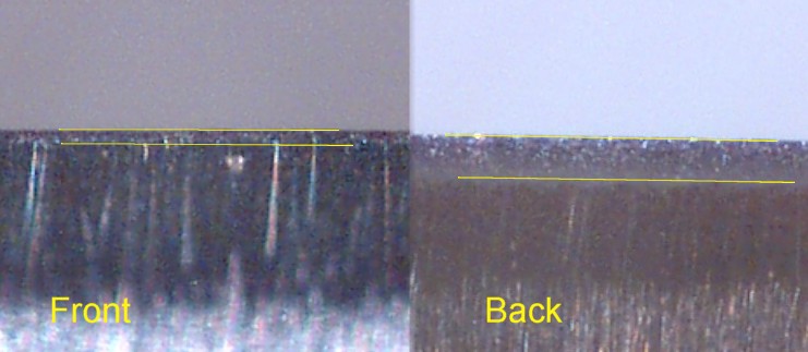
When you use a plane, the cutting edge pushes forward and down against the wood. The upper surface of the iron pushes against the shaving, pushing the shaving up and through the mouth. The lower surface of the iron pushes down against the work. The action of the wood on the iron actually grinds/hones metal away, producing what I call a wear bevel on both upper and lower surfaces. These pictures show both the front and back wear bevels.
This discussion applies equally to bevel down (normal bench planes) and bevel up (block planes, some bench planes) irons. It is important then to use names that do not depend on whether the bevel faces up or down. I use upper wear bevel for the wear bevel on the blade face which is upward during use - pushing the shaving up through the throat. Likewise, lower wear bevel applies to the wear bevel on the downward blade face which rubs against the work.
It happens that this is a bevel down iron, so the face labelled front faces down toward the work and has the lower wear bevel. The face labelled back faces up toward the shaving and has the upper wear bevel. It is typical that the upper wear bevel is the wider of the two by about this factor. [On a bevel up plane, the wide wear bevel occurs on the front of the iron!]
The area between the yellow lines is the wear bevel. The lower wear bevel is about 10 pixels or 0.0007" wide, the upper wear bevel is about 40 pixels or 0.0028" wide. The iron itself is actually shortened by about 0.0002" during use. This wear was the result of 200 passes along a 4 foot douglas-fir board.
These wear bevels are visible without magnification. If you hold a worn iron toward a light and tilt the blade back and forth, you will see a bright line along the edge. The angle at the edge between the line from the edge to the light and the edge to your eye should be about 90 degrees. Wear bevels are visible on both the front and back of a worn blade.
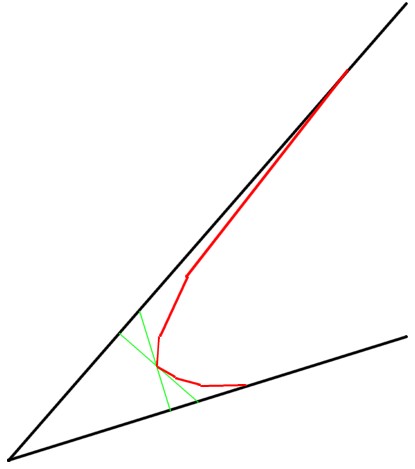 This is a scale drawing of a worn blade, based on observed test results. This interpretation is new as of Mar, 2006.
This time the blade is drawn as it would be in the plane. This plane has a bedding angle of 46.5 degrees. The blade was sharpened with a single front microbevel at 29 degrees, and a single back microbevel at 2.4 degrees. That is, the included angle was 31.4 degrees.
The black outer lines show the original microbevels. Once again the drawing is of the last 0.01" of the blade. The lower face (the clearance angle) is at 46.5 - 29 or 17.5 degrees. The upper face is at 46.5 + 2.4 or 48.9 degrees. The included angle is 31.4 degrees.
Before the test, each freshly sharpened face was scratched and the distance from certain features on the scratch and the sharp edge measured carefully. After the test (150 passes along the 4 foot test board) the distance from the same features on the scratch to the worn edge was measured. The shortening of the blade was 0.0013" (17 pixels), as measured on both the front and the back.
The green lines represent the observed shortening of the blade. The green lines are perpendicular to the faces because the microscope was perpendicular to the faces.
The worn edge must be at the intersection of these two green lines.
The width of the wear bevels was also measured. The wear bevel on the lower face was 0.00061" (8 pixels) wide, on the upper wear bevel almost 0.003" (40 pixels). So, we know where the wear bevels begin and end.
What do they look like between those points? In fact, I don't know. The red lines in the drawing are my current guess at the shape of the wear bevels.
This is a big change in my understanding of the shape of the wear bevels. I used to think the wear bevels were flatter, coming to a finer point with a smaller included angle than in this drawing. In fact, what you would get if you used steeper front and back microbevels. I now think the worn edge is blunt.
How blunt? If you use my jig when honing, you get a sharp blade as shown by the outer black line. The edge has thickness very nearly zero - it is sharp. At the point shown in this image, the worn edge has a radius of curvature of about 0.0005" (computed from the measurements above).
This is actually a 10 to 1 scale drawing of the 200X images taken of the test blade. This drawing corresponds to a magnification of about 2,000 times.
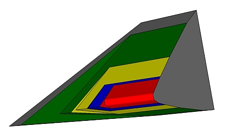
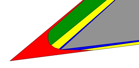
 This is a scale drawing of a worn blade that started out with 3 microbevels on the front and back. It is the same wear profile as above.
The bevels, starting from the edge: red is the wear bevel, blue is the remnant of the third microbevel, gold is the remnant of the second microbevel, green is the remnant of the first microbevel.
 This zoomed drawing shows the amount of metal removed at each stage.
A few thoughts about the upper wear bevel.
While wider than the lower wear bevel, the upper wear bevel appears to be much flatter. I cannot measure the exact shape, but it appears that the slope of the upper wear bevel near the edge is no more than a few degrees different from the last honed bevel. So, wear on the upper surface does not greatly affect the geometry of the planing action. The small change however might make the plane work a little better on hard woods, a little worse on soft or stringy woods.
The worn upper surface is rougher than a freshly sharpened surface and at a slightly different angle than it was before use. Does this roughness affect the planed surface? Does sharpening remove this roughness?
Standard sharpening practice works the back face in two different ways. First, most people flatten an inch or so of the back near the edge before the first use of the blade. Second, most people lap the back of the iron (often more than once) during each sharpening operation to remove the wire edge.
Are they smoothing this wear bevel each time they sharpen? I believe the answer is no, particularly if they lap with the blade flat on the abrasive. The only way to smooth the wear bevel on the back using this sharpening protocol is to grind the blade down the full width of the back wear bevel. Put another way, you cannot simply grind up to the worn edge. You must continue grinding until you have ground away the entire back wear bevel.
Getting the best edge must involve smoothing the upper wear bevel during each sharpening operation.
While wider than the lower wear bevel, the upper wear bevel is still quite narrow - no more than 0.004" wide. This means that all forceful contact between the shaving and the iron takes place within 0.004" of the edge. Even if you could operate the plane with the cap iron set 1/32" from the edge, this is still 8 times too far away for the cap iron to have any effect on bending and breaking the shaving.
It is my belief that the cap iron, as typically set, plays no part in breaking the shaving (it is still important for operation of the plane in certain plane designs). In most Bailey style planes, moving the cap iron close enough to the edge to have an effect in chip breaking is not possible - shavings would jam in the mouth of the plane.
A study of chip formation in front of a mechanized planer confirms this view. It showed that chip breakers set between 0.004 and 0.002" from the edge do improve surface quality. [This page disappeared in early 2005, but is mirrored on Steve Elliott's blade testing pages].
This study was done with a power planer. These planers have no equivalent of the front of the mouth pressing the fibres down in front of the blade. Even without the front of mouth equivalent downward pressure, the use of the very close cap iron was able to reduce tearout. This suggests that the same features could work in hand planes - wide mouth, very close cap iron. That is, open the mouth to avoid jamming, cap iron very close to the edge to reduce tearout.
| May 2012 |
| Steve Elliot and Bill Tindall have managed to get a translation of the original paper. The translated paper, titled The influence of the cap iron, by Chutaro Kato and Yasunori Kawai is on Steve's site. Here is the translated video which shows shavings being formed with a variety of cap iron shapes and positions. |
| Figure 5 in that paper shows the cap iron wear! With the cap iron very close to the edge there is significant wear in the cap iron. I don't recall anyone reporting cap iron wear with a hand plane. This is yet another reason to conclude that in normal use, the cap iron is not turning the shaving - the shaving has already been broken by the blade. |
One of the important benefits of using a cap iron may be its ability to remove heat from the area of the edge.
The rate of wear is a function of the temperature of the steel at the edge, with cooler blades wearing more slowly. You can feel that heat is being generated from the temperature of the shaving. It is a little harder to feel the temperature of the iron, but if you remove the blade quickly after a shaving session, you can feel the warmth there.
This heat travels down the iron, with some being picked up by the cap iron. A heavier cap iron with a greater surface area in contact with the blade will remove more heat, allowing the edge itself to run a little cooler. The smoother the contact surface (between the blade and the cap iron) is, the more heat will be transferred. It makes sense then to check the contact surface.
It might be interesting to repeat a test with a heat insulator between the cap iron and the blade - say a thin shaving.
The main contribution of the cap iron is to insert a spring into the system that holds the plane iron against the bed.
All the other blade holding parts are stiff. As such, they offer no adjustability. With no cap iron, if the lever cap screw is wrongly set then either the blade is loose, or you cannot operate the lever cap.
With a wooden plane and a wedge, the springy cap iron allows for some error in the fit of the wedge to the lower abutments. No cap iron and this fit has to be very close (the wood of the plane provides limited springiness).
I have read reports of a technique that may smooth the back wear bevel, for those who don't use back bevels.
The idea is that rather than just lapping the back with the blade flat on the abrasive, you elevate the other end of the blade slightly. Charlesworth apparently uses a thin ruler along his sharpening stone. With the blade perpendicular to the ruler, he slides the blade back and forth across on the stone. This is done as the final step, so only the highest grit is used.
The actual geometry is a little surprising. If you have a 2" wide stone and a 1/64" thick ruler, the distance between the edge of the ruler and the blade edge will be about 1-1/2", perhaps a little less. The microbevel angle will be about 0.6 degrees. If you remove 0.001" of metal perpendicular to the back at the edge, the microbevel will be 0.096" wide.
This should be enough to flatten the back (no other back flattening should be required). Because you are using a very high grit and working right at the edge, you should have a very good edge, the first time you use the iron. Since the wear bevel is only 0.0028" wide, this microbevel appears to solve the problem of honing away the wear bevel. I write appears because I have some unresolved questions about the exact geometry on subsequent sharpenings. [To do: Complete analysis of back wear bevel geometry through a series of sharpenings.]
|
David Charlesworth writes: "The ruler is stuck to one long edge of the 8000 or 10000 grit water-stone,
but the blade is moved across the stone not lengthwise, thus imposing scratches
at right angles to the edge, and hopefully honing away the last vestige of
wire edge!."
Moving the blade across the stone means that the honed bevel is an arc, not a flat. When I asked David about this, he replied: "I use a very short stroke, probably no more than 3/4 inch. The ruler is on one edge of the stone and the edge of plane blade moves on and off the opposite edge. {This avoids the hollow water-stone menace!} This is imposing a negligible back bevel of about 2/3 of a degree. Yes it must be infinitesimally curved, but not significantly. The width of this polished 'bevel', is about 1/32" to 1/16" and stays the same for the life of a blade." An interesting approach. I may try this myself some day to see how well it works. Perhaps I can get a microscope image of the resulting back bevel. Lie-Nielsen sells a video made by David which demonstrates this technique. |
Performance Impact
How much can smoothing the back wear bevel every time you sharpen improve plane performance? Tough question, but I would guess that the effect is small. I have taken pictures of back bevels after 50, 100, 150, and 200 passes along the 4' board. The wear bevel gradually widens as the test goes on. So, the back wear bevel is there almost as soon as you start planing. What benefits there are probably show up during the first few planing passes - something probably only important for final smoothing of difficult grain. [To do: Test blade using normal sharpening, then retest same blade without honing the wear bevel.]
This means that most plane users are planing with an angle at the edge of greater than 45 degrees. Most of the time their planes perform well with this slightly higher planing angle.
It depends on the included angle and perhaps the bedding and clearance angles to a small degree, but basically every worn blade will have the worn blade profile as shown above, no matter what its original geometry was. That is, with or without an original back micro bevel, it will have a back wear bevel during use!
As soon as you start planing, the blade shape begins to morph from the sharp blade shape to the worn blade shape. Most of the time the blade looks more like a worn blade than a sharp blade.
Most of the time you will be planing with a back wear bevel.
The lower surface of the iron rubs against the work. This rubbing has the effect of gradually grinding/honing a new bevel on the lower face of the iron. As more metal is ground/honed off, the wear bevel widens.
Let's use the above drawing of a worn blade, where the red lines are my best guess at the shape of the wear bevels.
The first thing to recognize is that the lower wear bevel is where all the contact between the blade and the work take place. The upper wear bevel is where all the contact between the blade and the shaving takes place.
As the two wear bevels widen and the included angle grows, the plane stops cutting easily.
There appear to be two reasons for the poorer cutting action of a worn blade. First, the larger included angle means a blunter cutter. Don't let the scale of this image confuse the problem. In fact, the part of the dull edge that is actually cutting is probably less than 0.0004" wide. This is still a pretty fine cutting tool.
Second, the shape of the lower wear bevel. As you push the plane forward it tends to surf along the wood - to rise up out of the wood. As the lower wear bevel widens, this tendency increases. The person using the plane notices this and increases the downward pressure. This works for a while, but with increased pressure you also get increased friction, leading to increased heat and increased wear rate.
The difference in planing action as the blade goes from very sharp to too dull to use:
A freshly sharpened blade has an edge that is very very thin - too thin to see even at 200 times magnification. A surface 1 pixel wide at 200 times magnification is visible with this microscope. Since there is no visible surface area to the edge, the edge width is less than 1 pixel wide - less than 0.00007" wide.
I believe the edge is much less than this minimum visible width. Assuming the lower face of the edge is about half this width or 0.000035" wide, then the surface area of a 2" wide sharp iron edge is 0.00007 square inches. If you exert a downward force of only 1 pound, the force the edge itself applies to the wood is over 14000 pounds per square inch. The wood easily deforms under this pressure, which is why a reasonably heavy plane with a sharp iron and a flat sole can take shavings with no additional downward force.
During use, the lower wear bevel forms. After even one pass, I believe there is a very narrow wear bevel right at the edge with clearance angle of zero degrees. The plane still cuts and cuts well. The wear bevel is so narrow that the area of the surface pressing down on the wood is still very small. So, the effective pressure is still very high. With any forward movement, the blade is easily driven down through the fibres.
However, as the width of the wear bevel increases, the plane performance decreases. It is hard to tell the difference in performance between a freshly sharpened plane and one with a wear bevel up to 2 or 3 pixels wide. When the wear bevel reaches 6 pixels (0.00043") the plane still works reasonably well, but you can tell the difference.
When the lower wear bevel reaches a width of 8 to 10 pixels, the surface area of the lower face is at least 16 to 20 times as great as that of a freshly sharpened blade. The pressure the iron exerts on the wood is reduced by the same factor. Instead of 14000 pounds per square inch, the effective pressure is between 700 and 875 pounds per square inch. With this decreased pressure, the dull iron is no longer able to cut into the wood fibres.
The downward pressure the blade exerts on the wood is matched by the upward pressure the wood exerts on the blade. Thus, the upward pressure is also 16 to 20 times as great. This pressure must be resisted by the blade holding mechanism - the frog, the cap iron, the lever cap, the iron itself. As pressure increases the blade deflects slightly, reducing the set of the iron. You can continue planing if you increase the set and increase the downward pressure.
Increased downward pressure causes work surface deformation and in a sag in the bench top. As well, increased effort seems to result in a reduced ability to sense what the plane is doing and get feedback from the wood. Eventually, usually a few passes later than optimal, you have to resharpen the blade to remove the lower wear bevel.
 The model shows a worn blade, along with how it got there.
Starting from the left:
The model shows a worn blade, along with how it got there.
Starting from the left:
The question now is: how to resharpen this worn blade using microbevels on the front and back?
 The simplest honing strategy is to
This model shows what happens. The new first microbevel on the upper surface (the first back bevel) is now much longer than we want it to be. The longer the back bevel the more time it takes to hone. The same problem arises with the front bevel - each time we hone the first front microbevel gets longer. After a while we can grind the primary, shortening the front microbevels. We cannot do this with the back bevels.
Since we cannot easily correct a back bevel that is too long, we must prevent it happening. A honing strategy that keeps the first back microbevel width the same produces much better results with much less effort.
 Our approach to honing is shaped by the need to limit the size of the first back microbevel. The wider it gets the more time we spend during the next sharpening. When the first microbevel on the front gets too wide we shrink it by grinding the primary. We can't do that on the back. So, we have to avoid making this first back microbevel too wide.
Keeping the first back microbevel a reasonable size determines the whole honing strategy.
This model shows the results of honing the first microbevels.
The new first back microbevel just extends into the old second back microbevel.
 Once you have the first microbevels on the front and back, you continue with the second and third in the usual way. In this model, also to scale, we now have 7 different states. From the left:
After this second honing, the back microbevels have the same widths as after the first honing. The front first microbevel is as wide again as after the first honing. On each honing the front first microbevel widens by the original width. When this gets too wide - around 1/16" - it is time to grind the primary again. This grinding removes all but 0.01" of the old wear/micro bevels.
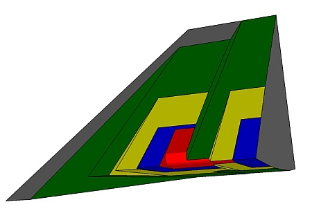
 A final model - the newly honed blade, with shadows of the former bevels of all types shown on the slice on the left side.
The back bevels face up, the front bevels face down.
Your first back microbevel should be less than 1/32" (.8 mm). If it is more than this spend more time on the front microbevels and less time on the back microbevels.
 When you sharpen an iron for a bevel down plane, the microbevel angles angles are the same. The difference is that the front bevels face up and the back bevels face down. This model shows a plane iron with standard front and back microbevels, but with the front bevel facing up. You can see that the microbevels on the back (downward) have shallower angles than those on the front (upward).
How does this small change affect the sharpening problem?
 Wear on the blade in this position is the same as for a bevel down iron - short steep wear on the bottom face, long much flatter wear on the top. This wear bevel has the same shape as the wear bevel in the bevel down example above.
At the tip of the blade, the wood and the shavings interact with the blade no differently than if it was bevel down. Back from the edge there may well be differences; at the edge, there are none.
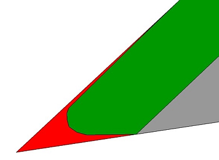
 The model shows the blade after the first microbevels on the front and back. As in the bevel down case, the first microbevel on the back (lower face here) does not reach the worn edge and the first microbevel on the front (upper face here) removes the entire wear bevel as seen from the front. As seen from the back, the entire wear bevel is still present.
If you hone without microbevels, this is more or less what most people would have as their final result. From the front, all wear is gone. From the back, the blade is a dull as when you started sharpening.
 This model shows
Notice that the wear bevel is not completely removed until the third microbevels are done.
The total width of the microbevels on the back is the same as the previous honing. The total width of the microbevels on the front has increased by the original microbevel total width. When the total front microbevel width exceeds 1/16", it is time to regrind the front primary bevel, leaving only 0.01" of the old microbevels.
 In this section, we compare what happens during a sharp-dull-sharp sequence as measured with the model that used front and back microbevels, versus the model that uses a single front bevel.
The comparison assumes the same final included angle and the same wear.
This is the microbevel drawing, in two dimensions. The tip is the edge after the first sharpening, before use. The red shows the metal worn away during use. The green, yellow and blue show the metal removed during the second sharpening. The grey point is the second sharp edge.
 This is the comparable drawing for the single bevel case. The tip is the edge after the first sharpening, before use. The red shows the metal worn away during use. The grey shows the tip after the second sharpening.
The shortening of the blade is 4 times as great using single bevel sharpening.
The total amount of metal removed is also 4 times as great using single bevel sharpening. This means you either use coarser abrasives or spend a lot longer sharpening.
| Pitch | Angle |
| Common | 45 |
| York | 50 |
| Middle | 55 |
| Half | 60 |
If you are getting tearout problems you can increase the back bevel angle by making a jig with a taller short jaw. Assuming the tall jaw is 1.75" then you can use this table to find a short jaw height to create any desired back bevel. Or, you can make a wooden slip with thickness equal to the difference between the actual short jaw height and the height in the table. NOTE: The angle shown here is the final back bevel angle, assuming you use the two standard slips when honing the back bevel.
| Short jaw height | Back bevel angle | Effective angle |
| 1/8" | 3.6 degrees | 48.6 |
| 1/4" | 6 degrees | 51 |
| 3/8" | 8.1 degrees | 53.1 |
| 1/2" | 10.2 degrees | 55.2 |
| 5/8" | 12.2 degrees | 57.2 |
| 3/4" | 14.3 degrees | 59.3 |
| 7/8" | 16.3 degrees | 61.3 |
| NOTE I would dedicate an iron to a particular back bevel angle rather than using a single iron and changing the back bevel to suit the wood. While it is easy to increase the back bevel angle, it is much harder to decrease the back bevel angle. The proper procedure for removing a large back bevel is to grind the front primary bevel until the entire back bevel has been removed, then start honing. This is slow, involves regrinding through the existing edge, and shortens the blade. It is much better to dedicate a blade to the steeper back bevel. |
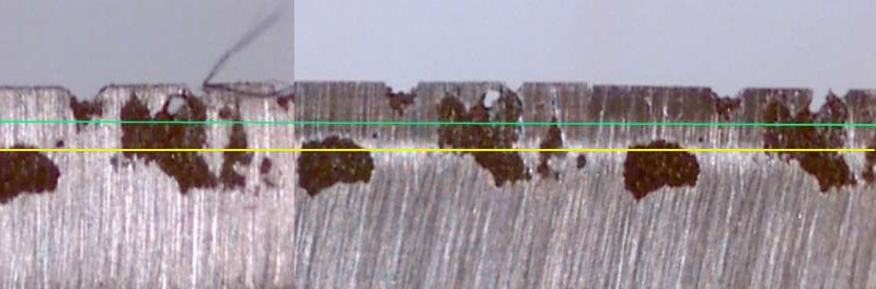
All pictures of the back microbevels at 60 times magnification (there are 3 pictures, but you have to look closely to see the join between 2 and 3). From 15 micron on left to 0.5 micron on the right. The yellow line shows the limit of the 5 micron microbevel; below that in pictures 2 and 3 it is remnant of the 15 micron microbevel. The green line shows the limit of the 0.5 micron microbevel; below that in picture 3 is the remnant of the 5 micron microbevel.
This blade worked very well, cut cleanly and lasted well, in spite of the small pitted area.
Check out my jig page for a simple jig you can make in your shop, along with a sharpening set up using sheet abrasives, that reliably produces excellent edges, for all types of irons.
Return to the Sharpening home page.