|
| Jig Geometry |
|
| Finest abrasives. | ||
| Microbevels front and back. | ||
| Use a jig. | ||
| Copyright (c) 2002-15, Brent Beach |
When I sharpen I add two additional requirements of my jigs. First, the jig must allow me to work both sides of the edge tool - often at very different angles. When sharpening a plane iron, the angles are different - front angle around 30 degrees, back angle less than 5 degrees. When sharpening a knife the angles are almost always the same - from 10 to 30 degrees or more.
Second, the jig must allow the use of microbevels - small increases in the sharpening angle to focus the abrasive action at the edge.
Since we have three functions - hold the tool, hold the abrasive, create microbevels - we actually have three jigs. In most of these pages when I use the term jig I mean the tool jig. On this page, since there are three different jigs, I use the full name for the jig:
When it comes to holding a tool steady, the friction forces between wood and metal make for a very secure grip. A tool jig made of metal that is trying to hold a metal tool has more problems with the tool twisting in the jaws.
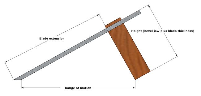 This is the simplest tool jig that can maintain the angle. It grips the edge tool on both sides. The angle is determined by the extension - the distance from the edge to the front of the tool jig, and the height - the distance from the top face of the tool to the bottom of the tool jig.
The third length marked on the model is the range of motion - the distance from the back of the bevel to the front of the tool jig. This is the amount you can move the tool jig back and forth with the bevel on the abrasive but the tool jig not reaching the abrasive.
If the tool you are sharpening is a 7" plane iron then the front of the tool jig can be up to 6" from the tool edge, which allows a tool jig height of almost 3.5" and a range of motion of almost 7".
However, if the tool is a 3" butt chisel, or a 2" plane iron for a very small plane, the numbers don't work out quite so well. You need about 1" of the tool inside the tool jig, leaving only 2" of extension in the chisel case. This means the range of motion is only 4". In the short plane iron case, the range of motion is only 2".
A different tool jig design is required to get a long range of motion for short tools. Or just to get a longer range of motion for longer tools.
The second case arises when you are using bench stones. If you use only part of the stone then the stone will dish in the section you are using. The dishing shape reflects the pressure you apply during the motion - more pressure in the middle means more dishing in the middle. If you can extend the range of motion to include the entire length of your stone, the dishing will be limited to the area near the ends, with the middle portion remaining fairly flat.
 In this drawing the extension is the same as in the previous drawing, but the range of motion is much larger.
You can select the angle for your tool jig depending on the length of your tool and the range of motion you want.
Jigs with rollers usually use the surface of the abrasive as the abrasive jig. This solution has several problems. When the abrasive is a bench stone the problems are:
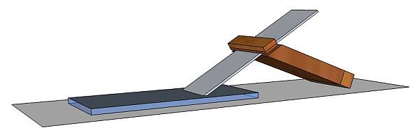
A wooden sliding jig which slides only of the glass solves all three problems. Correct tool jig design allows you to use the full length of the abrasive. The tool jig slides on glass eliminating wear. The abrasive does not dish, so the abrasive plane and the tool plane remain parallel.
 A glass sheet is a very good abrasive holding jig when you use sheet abrasives (not so good with bench stones!) and sliding tool jigs.
Glass is relatively inexpensive. When used with wooden tool jigs it never wears out or goes out of flat. The tool jigs also wear very slowly - not at all if you keep the glass free of abrasive particles.
The abrasive is always in the same plane as the sheet of glass, so the tool jig is always riding on a parallel surface.
The sharpening station that uses sheet abrasives on glass is discussed on these pages.
The abrasive jig is shown here with the square tool jig, but it works just as well with the slanted tool jig.
 With bench stones there is a problem with getting a plane parallel to the plane of the stone. For one stone it is not too much of a problem - you can build a platform the thickness of the stone. Of course, as the stone wears you have to keep changing the height of the platform.
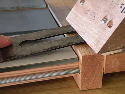
This picture shows what I call a stone vice - a vice like contraption that holds the bench stone in the same plane as the surface of the vice. This page shows other versions of bench stone holding vises.
 If you look at the stone vice page you will see one that more closely resembles this model. The jig is sized based on your bench stones and the threaded rod you use. The height should be about 1" more than your thickest stone. The total width for a jig that holds 3 stones is the width of your stones plus 4 times the diameter of your threaded rod plus 1.5". The gap between the jaws should be at least a little bigger than the length of your longest stone. You can provide for longer stones by using longer rods. My jig allows for stones a bit longer than 12" (some diamond stones are 12" long).
Having a very long stone and only using part of it may lead to problems related to uneven wear along the stone. You should design your sharpening jig to ensure you can use the full length of your stones. For most tools that means using a slanted sharpening jig.
However, you must also make your stone vice wide enough as well - at least as wide as the widest stone you intend to use, and probably an inch or two wider so you don't slide off.
 The vice does not actually hold the stones - it holds wooden blocks that support the stones. You ensure that the surface of the stone and the glass sliding surface of the abrasive jig are parallel by flipping the jig over and resting it on the table. Put the bench stone on the table top, then the support block on the stone. Tighten the nuts then flip the whole back over. Since the stone vice grips the support blocks, the bench stone will drop out when you lift it off the table. Put it back on the support block when the stone vice is in position.
 Here is a stone vice (an abrasive jig) with 3 bench stones. The stones are all drawn as having the same thickness, but that is not a requirement.
As well, the bench stones need not be stones! I have put sheet abrasives on plate glass 8" by 3" by 1/4" and used them in the stone vice (see image below). Since the glass rests on support blocks, the vice puts no pressure on the glass itself.
Note that this model is a little misleading. Assuming the grits go from coarse to fine, when honing on the middle abrasive the jig should be resting on a slip to produce the first microbevel. The model below shows the slips as well.
 Eventually it occurred to me I could change the geometry by putting a wooden slip under the jig! Since I wanted two micro bevels, I needed two slips.
The thickness of the slips depends on the type of jig used. When I first did this my jig was a square jig 1.5" tall. Appropriate slips were 0.06" and 0.10". With the large slanted jig I (5" along the front face, 50 degree angle) the slips are 0.18" and 0.27". The extension calculator will help you determine appropriate slip thicknesses for your particular jig design.
This method works well with glass and also works with the stone vice and bench stones.
NOTE:It looks like the stones are raised in this model. You can see the front of the stones because the stones are shorter than the wooden supports. This means there is a small gap between the front of the stone and the glass on the narrow jaw.
 An alternative to raising the back of the jig using slips is lowering the stones. This works with the stone vice, does not work with sheet abrasives on glass.
Rather than put the slips under the jig, put the slips under the stones when setting the stones in the jig. So, first put the slips down: the thin slip under the medium grit, the thick slip under the fine grit, nothing under the coarse grit. Then the stones on top of the slips. Then the support blocks on top of the stones. Then setting the stone vice around the whole thing and tighten the wing nuts. When you flip the whole thing over
There is a down side to lowering the stones, as this picture shows. The range of motion is limited on back bevel honing because the back of the tool hits the front of the vice.
Notice that the stones in this case are sheet abrasives on glass blocks. When I did this I called it slipless stones and went through the development.
 A reader of these pages, Randy Klein, extended these ideas and got around the problem of one of the stones being lower than the glass surface. While he used MDF blocks of varying thickness, you can get the same effect by using glass plates and setting the heights on an uneven surface.
The basic idea is to add enough material to both sides of the tool jig so that they are both effectively thicker by the large slip thickness.
To get a setup equivalent to slip thicknesses 0.1" and 0.15" (for example) in a conventional setup, we use 4 buttons with thickness 0.15", two strips of thickness 0.15" and two slips of thickness 0.10".
The white tiddly winks in the corners support the stone vice at 0.15". There are no slips under the coarse stone. The 0.10" slips support the medium stone. The 0.15" slips support the fine stone.
 After setup, with the wing nuts tight, when you flip it over the coarse stone is 0.15" above the glass, the medium stone 0.05 above the glass, and the fine stone level with the glass.
With both jaws of the tool jig thickened by 0.15" you have the equivalent system.
Randy Klein describes his version in this thread on the Sawmill Creek website.
 The last section mentions the idea of a thicker jig. With a square jig, adding 1/4" to each side is simple. For a slanted jig, the amount you add depends on the slant you use.
This model shows a modified slanted jig - modified to allow the abrasive to be 1/4" higher than the surface on which the jig slides. This jig has a 50 degree slant (angle at the front of the jig at the blade).
The darker brown indicates the original jig size, the lighter brown the thickening required to compensate for the raised abrasive surface. The larger jaw is lengthened by about .7", the smaller jaw by a little more than .25".
I have no extension calculator for this sharpening model for slanted jigs yet. If enough people express interest I will develop one.