|
| Fads and fallacies |
|
| Finest abrasives. | ||
| Microbevels front and back. | ||
| Use a jig. | ||
| Copyright (c) 2002-15, Brent Beach |
To summarize, all of the stropping compounds that I have tested have larger abrasive particles than the 3M 0.5 micron microfinishing abrasive. On the basis of my testing stropping can only produce worse results.
How then to account for all the people who claim that stropping helps? If stropping helps, then there is something else they are doing during honing that they should change -- use different abrasives, use a different honing technique. Stropping will only help if you bring an inferior edge to the strop.
As in the case of stropping, if you are able to touch up a blade and return it to its original sharpness, then you must not have started with a sharp blade.
Early in my blade testing, when looking at the upper surface of plan irons, I noticed that the wear on the upper surface was all near the edge. How near? Within 0.004" of the edge.
It occurred to me that this meant that the upper surface within 0.004" of the edge was breaking the chip, not the chip breaker that was set about 10 times farther back from the edge. This was when I started calling the second iron a cap iron.
In this rather extended discussion, I will suggest that most of the time the second iron does not break the chip. In fact, for many people, it has never broken the chip and never will. For some people who are working particular kinds of wood, who have achieved a high level of expertise in woodworking, and who have read enough in the right places, the second iron will some of the time, break chips.
Rather than name the second iron for a feature that is almost never used, I prefer to use the term cap iron, a name for the function that it always performs.
For a component of the plane that is often overlooked, the complexity of the function of the cap iron is counter-intuitive. This discussion attempts to look into all the nooks and crannies. If you interested, I hope the information you need to satisfy your interest is here. Somewhere here.
First, then, the reasons why I believe that the cap iron is only rarely needed for chip breaking. (This does not mean you don't need the cap iron, just that a lot of the time it does no chip breaking.)
 My examination of the upward facing surface of plane blades after use (see my bevels page) made it clear to me that all of the forceful contact between the shaving and the blade occurred within 0.004" of the edge. After moving that far past the edge, the shaving had curled away from the upper face of the blade. The fibres in the shaving had bent or broken. Those fibres were no longer able to exert sufficient force back along the shaving to lift fibres ahead of the edge - the cause of tearout.
The shaving does slip along the upward face before it clears the mouth, no question. Some small forces are involved in this. However, those forces are not strong enough to cause wear on the upper surface of the blade. They are not the cause of tearout.
How close is 0.004"? Most people aim to put the edge of the cap iron about 1/16" from the blade edge. This is 0.0625" or about 15 times too far from the edge to have any effect on breaking the fibres. A very close set would be 1/32", 0.03125 or about 8 times too far from the edge. Even at 1/64th of an inch, the cap iron is 0.015625" or almost 4 times too far from the edge.
All my testing was done with shavings between 0.001 and 0.002 inches thick. I took thin shavings to conserve my test wood. With thicker shavings I would use up too much wood. If you are taking much thicker shavings the chip may wear the back farther from the edge.
 US Patent 540283, June 4, 1895, by Justus Traut and Christian Bodmer (two of the main inventors in the Stanley brain trust in the 1890 to 1910 period) is the source for the drawing at the right.
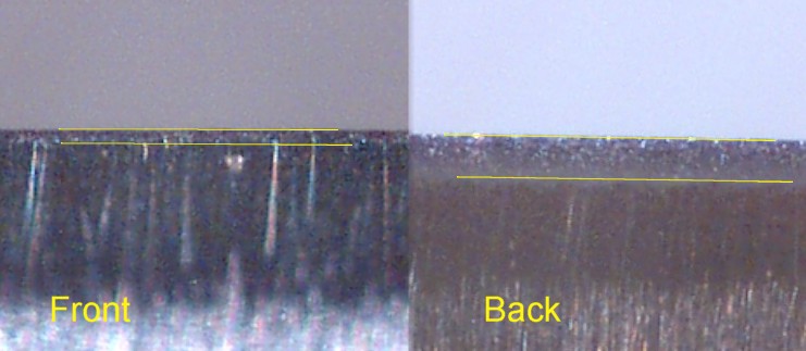
Traut and Bodmer distinguish between the front (near the edge) and back (the other end, away from the edge) parts of the cap iron. They call the whole cap iron the "knife-controlling member". The back part, which includes the cap iron screw and the slot for the depth adjust lever, they call the "knife-actuator". The front part, from 7' at the edge to 7'' just back of the bump, is the "knife-edge cap".
Rather than use a heavy cap iron, the idea behind this patent is to weaken the cap iron at the point numbered 12, in one of four different ways, to let the "knife-edge cap" pivot more easily around the fulcrum at 12. The effect is that the pressure of the lever clamp is transferred more or less equally to the front (7') and back (7'') of the knife-edge cap.
This goal of distributing the force to two locations is a departure from some earlier cap irons. I have several old wooden planes with equally old double irons. Those cap irons are arched from the edge to the cap iron screw. The clamping pressure in this case is only at the end of the blade. In fact, tightening the cap iron screw causes the blade to arch, even before the irons are in the plane and tightened into position by the wedge.
Traut and Bodmer do not say the cap iron breaks chips. Rather, one of its functions is "to properly turn the shaving in the throat of the plane, as said shaving is stripped, by the knife-edge, from the body of the piece being planed". That is, it prevents clogging. It plays no part in reducing tearout.
I don't know that this patent was ever actually implemented by Stanley. Something like it was eventually produced by Record - their two part cap iron.
 One other small note. The perceived need to weaken the cap iron just back of the knife-edge cap implies, at least to me, that they thought that having a strong connection here was a limitation of existing cap irons.
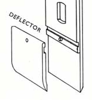
The left is from the Stanley patent, the right from the Record user manual for the Stay-set Cap Iron.
What changes when you make either of these modifications? First, depth setting is unchanged. Forces along the blade are still effective. Second, twisting of the knife-edge cap, particularly in the stay set case, seems to be prevented as well. The only direction of motion left is perpendicular to the blade.
Both of these designs lessen (the Record design eliminates) the ability of the cap iron itself to hold the knife-edge cap on the blade. Both designs rely on the lever cap for that function.
Can it be more than that? Were these designers concerned that, during use, a conventional cap iron acted to lift the knife-edge cap off the blade? These designs would reduce that effect.
If so, what does that say about newer, heavier, cap iron designs. A heavier cap iron would increase any lifting effect.
I guess the new cap iron designers know more than Justus Traut and Christian Bodmer. The new designs probably have been extensively tested. The results of those tests must conclusively disprove the ideas of this section. I have looked around for those test results without success. If you should run across them, could you send me a link? I will add it here.
It is important to be quite careful here because we have two separate issues. The first issue, do cap irons play an important role in hand planes. The second issue, is that role primarily or at all related to chip breaking.
As we go through the positive evidence, we will distinguish these two cases.
For normal work a compromise is effected, fitting the back-iron about 1/16 in. from the edge. When a piece of wood with difficult grain has to be planed, the back-iron is advanced and the plane set as fine as possible.Hayward uses the term back-iron rather than cap iron or chip breaker. He is not very precise in how far you advance the back iron to work difficult wood. In this sentence, I an inclined to think that the phrase the plane set as fine as possible is not a reference to the back iron, but to the actual depth of cut. A very fine shaving is much less likely to produce tearout.
Would the average new woodworker understand that these two sentences meant that you should move the cap iron to within 1/256 inch of the edge if you are getting tearout? If the chip breaking function of the cap iron was essential knowledge, would an introduction to the plane spend so little time explaining, and be so vague about, something that was important?
The Hayward book may be damning the chip breaking action by faint praise.
I would rate this as positive on cap irons, unclear on chip breaking.
According to this book, the second iron first appeared in Europe in the late 1700s. It was originally not at all like the Stanley cap iron. Originally it was simply described as
a tool in which one puts two irons, bedded back to back, one on the other, the bevels opposite, with the iron bedded as usual. ... The bevel of the upper iron lifts the shaving higher. The two bevels must not meet at a line; the lower iron should be advanced a bit farther. The more in advance of the upper iron, the more tearout.This is my clumsy translation. It is clear that while no French planes had this mechanism, and thus handled tearout in other ways, the Germans had started using two irons for difficult wood.
This is pretty clear evidence that the set of the cap iron alone determined the amount of tearout. However, it is clear that the author had not actually seen such a plane in action. This is hearsay only.
 Volume 2 of Holtzapffel - Turning and Mechanical Manipulation, contains a reference to an invention of Williams in 1825.
The geometry (assuming the diagram is accurate): bed 50 degrees, lower bevel 20 degrees, upper bevel 10 degrees. The articles says that Williamson actually made several of these planes.
The point of the invention was to produce a single iron plane that was "superior in its operation to the double iron that is adopted in the best planes". [Williamson 1825, page 86]. This single sentence tells us that:
The article also discusses the difficulty in laminating a cast steel (high carbon steel) bit to a cast iron (low carbon steel) blade. It says that early attempts were failures and the idea had been abandoned by the time of this invention.
It says that an attempt to use a cast steel lower blade with a cast iron upper blade also failed.
This invention used a single cast steel blade with bevels of about equal length, but different angle, ground on both sides.
This invention was also a failure. Holtzapffel 1856 explains that there were practical difficulties grinding the two bevels, and it was much easier to just use a plane bedded at 60 degrees.
I suspect the solution to the lamination problem, which put a cast steel bit on the back of a cast iron blade, doomed this invention. To make use of a laminated blade the honed edge must be in the steel bit, not in the middle of the blade (as this invention requires).
It is interesting to me that the idea of a honed back bevel as opposed to a ground back bevel did not arise. They must have just known that only grinding was possible and that grinding was an imprecise operation. Given those assumptions, microbevels could not be part of the solution space.
|
Cheap flat glass
My jig relies on the existence of inexpensive flat glass. When thinking about why the folks back in 1825 did not think of making a jig that slid on glass, it suddenly occurred to me to check when our common float glass was invented. From Wikipedia - Full scale profitable sales of float glass were first achieved in 1960!!! Staggering. Without a smooth surface on which a wooden jig could slide without wear, a jig like mine would be impossible. That hardly explains though why it took me 42 years, from 1960 to 2002, to invent my jig! |
 1886
1886
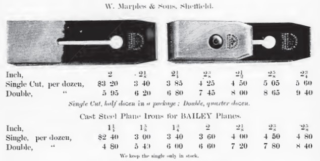
Marples laminated irons, tapered. The cap iron appears to be fairly flat on the leading face. The cap iron is arched and quite thick.
No drawing, but the Stanley irons are priced here. Notice the warning - We keep the single only in stock. This is not a preference for single irons, of course. People wear out irons, not cap irons, so cap irons would rarely be needed for replacement blades.
The fact that people would almost always be buying replacement irons and re-using their old cap irons even if from a different blade, may have reduced demand for cap irons. Lower demand for separate cap irons may have resulted in higher prices.
 1886
1886
The relative dominance of double irons is suggested by the page showing wooden planes. All of the bench planes offered in this catalogue had double irons.
Looking at the irons in the previous picture, a 2" double iron cost about 50 cents. A new smoother with a 2" double iron cost 98 cents. The smoother body then was almost half the cost of the entire plane.
A 30" jointer with a 2 1/2" double iron cost $2.25, the double iron costing about 66 cents.
A quick look suggests that these planes cost about 5 cents per inch, plus the double iron.
 1900
1900
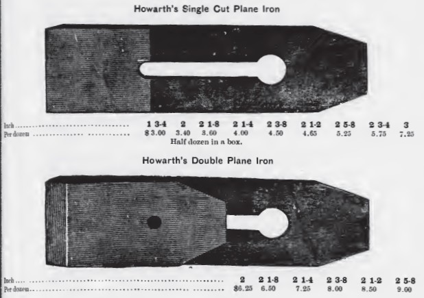
Howarth laminated irons, tapered.
The cap iron has a flat bevel. The cap iron bevel angle looks to be smaller than the blade bevel.
The chip lifting effect here is very limited.
 1900
1900
They wanted you to see the trade mark on the Stanley, so they put it on the wrong side of the blade.
The patent was issued Apr 19, 1892. It was based on switching the hole for the cap iron screw from the top of the slot to the base of the slot. The patent notes that this means that there is no enlargement at the top of the slot to interfere with the operation of the lateral lever. This only matters with a much worn iron.
This improvement in plane irons was introduced at the same time as Stanley started to add Lateral levers to their planes. It was introduced not to change the chip-breaking ability of the cap iron, but merely prevent problems with the lateral lever on worn irons.
The pitch of the leading face of the Stanley cap iron is greater than that of the English cap irons shown above.
Here I list a number of advantages aside from chip-breaking. These are ideas of mine (and other people). None have been tested and shown to be correct.
Small bevel up planes use a different depth setting mechanism - teeth on the adjuster engage notches on the underside of the blade. A bevel up plane cannot have a cap iron configured near the edge, so an alternative depth adjustment design is essential. The alternative used in bevel up planes appears to only be used when a cap iron is not possible. This suggests that the depth set mechanism based on the cap iron is so much better, it is used whenever possible.
The use in depth setting would have been important only after the introduction of steel planes. Double irons appears and quickly dominated the workplace long before that.
Testing - why is depth setting using a cap iron so much better than depth setting using the block plane mechanisms? It would appear to be necessary to build an entire plane with a single iron and a block plane style depth adjustment to test this idea directly.
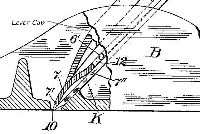 To explain this cap iron function, I am going to use the Stanley patent drawing discussed above, with the slight addition of a label pointing to the lever cap.
One crucial determinant of plane performance, along with blade sharpness and correct sole geometry, is that the plane iron be held firmly against the bed. In metal planes that is done with a lever cap of some kind. In wooden planes it is done with a wooden wedge.
In this diagram, pressure from the lever cap is applied to the cap iron. The cap iron is elastic. It deforms slightly under the lever cap pressure. This elasticity ensures that there is a tight fit between the lever cap and the cap iron across the entire width of the blade. Thus pressure is transmitted from the lever cap, through the cap iron, through the blade, to the bed.
Because the cap iron is arched, pressure is applied to the plane iron across the entire blade in two lines of force - one near the bevel, one an inch up the blade. The result - the blade is firmly pinned to the bed across its entire width along two lines of force.
Why is this a good thing? Why does this add significantly to the performance of the plane?
Think of the wooden wedge and how its shape changes over the lifetime of the plane. Because the wedge is driven in until it binds between the abutments and the blade, there will be lots of pressure holding the blade against the bed. If the tips of the wedge or the mating part of the abutments are worn, that pressure will not be where it is required to prevent blade vibration.
Now add an arched elastic cap iron between the wedge and the blade. As the wedge is driven in, the tips of the wedge move past the arch of the cap iron. The increasingly thick wedge presses harder and harder on the arch until that pressure is enough to stop further forward movement of the wedge. That is, pressure from the abutments through the wedge is concentrated on the top of the arch of the cap iron. Even if there is some wear in the wedge or the abutments, that is the only place the wedge makes forceful contact, so that must be where the pressure is applied.
The two facts - the pressure is through the cap iron arch and the wedge will move forward until that pressure is sufficient to stop wedge movement - ensure that the iron is well bedded.
The cap iron then serves to ensure that force from the wedge is applied to the blade near the edge.
A name suited to this function? The wedge force concentrator iron.
I am not saying that a well made wooden plane in good fettle will not work well with a single iron. I am saying that a poorly made wooden plane or a well made wooden plane in poor fettle will still work well with a double iron.
The issue of deformation of the lever cap with use does not arise.
However, the insertion of an elastic cap iron between the inelastic lever cap and in inelastic bed is crucial. Any alignment problems, any small errors in lever cap position, are compensated for the the flexibility of the cap iron.
In the case of a lever cap, there were no abutments to press the lever cap against the cap iron. The lever cap relied on its rigidity and its thickness. But a thick lever cap would hinder movement of the shaving unless the lever cap ended well back of the edge. The cap iron severed to transfer the force from the lever cap back of the edge to the thin cap iron edge near the blade edge.
I am not saying that a well made metal plane in good fettle will not work well with a single iron. I am saying that a poorly made metal plane or a well made metal plane in poor fettle will still work well with a double iron.
The test used a surface planer (large machine which pushes the wood quite slowly past a stationary blade with a solid chip breaker -- very similar to hand plane action) and a microscope to watch chip formation.
The blade was sharp with an included angle of 30 degrees, clearance angle 10 degrees. The chip breakers were thick (look to be more than 1/4" thick) with flat front face, one with 50 and one with 80 degree included angle. (A quick check of a couple of Stanley cap irons found an average included angle of around 50 degrees, but the face is convex rather than flat.)
The grain on their test board sloped down at either a 7 or 14 degree angle.
With very shallow cuts (0.002"), there was no tearout. With deeper cuts a chip breaker was required. For a shaving of 0.004", the 50 degree chip breaker 0.004" from the edge eliminated tearout. The 80 degree chip breaker could be set twice as far back from the edge and still eliminate tearout.
How close is 0.004"? Most people try to get the cap iron 1/16" or less from the edge. That is 0.0625" or about 15 times too far to make a difference.
If you do set the cap iron this close (and people have), you will often have a problem with the shavings jamming between the cap iron and the front of the mouth.
The paper describing this experiment was originally here. This page disappeared in early 2005, but is mirrored on Steve Elliott's blade testing pages. Steve has done some testing with a cap iron set this close to the edge, and it does help reduce tearout.
| May 2012 |
| Steve Elliot and Bill Tindall have managed to get a translation of the original paper. The translated paper, titled The influence of the cap iron, by Chutaro Kato and Yasunori Kawai is on Steve's site. Here is the translated video which shows shavings being formed with a variety of cap iron shapes and positions. |
|
Figure 5 in that paper shows the cap iron wear! With the cap iron very close to the edge there is significant wear in the cap iron.
I don't recall anyone reporting cap iron wear with a hand plane. This is yet another reason to conclude that in normal use, the cap iron is not turning the shaving - the shaving has already been broken by the blade. This also means that if you do set up your plane to take advantage of a very close cap iron, you will have to maintain/flatten the wear face of the cap iron. Between wear contact with the wood and wear during repeated flattening, you will start to use up your cap irons! This is not necessarily a bad thing. If you have a wood that cannot be planed any other way, then wearing out a cap iron is worth it. |
If you are removing heavy shavings and getting tearout, you should try moving the cap iron forward. Of course, this may result in the shaving jamming in the mouth. Correcting that will require that you move the frog back, or use a wider mouthed wooden plane.
This would appear to contradict the generally held view that a tight mouth is key to reducing tearout.
In any case, if you need to take thick shavings and you are getting tearout, you may try moving the cap iron forward. If you try different cap iron setting when taking heavy shavings and get differences in tearout, I would be interested in hearing about your experience. If you do some experimentation and get no change in tearout, I would be interested in hearing about that too!
Difficult grain can be handled by a combination of techniques: fine set, increased planing angle, very tight mouth, cap-iron-very-close-to-the-edge.
While some cap-iron-very-close-to-the-edge enthusiasts now claim they were doing that all along, there is very little evidence in my reading that this was a generally taught or generally used practice. Some early writers said the cap iron should be close to the edge but did not recommend settings close enough to make a difference in chip breaking.
With some woods, cap-iron-very-close-to-the-edge may well be the preferred approach.
I think everyone should spend a rainy afternoon in the shop experimenting with cap-iron-very-close-to-the-edge to find out when and how well it works for them. Remember though, very close means within 0.004 inches (0.1 mm).
 It is widely believed that before you can use a plane iron, the back must be flat. The origin of the idea probably went something like this:
In fact, the whole notion that flattening the back makes any difference to the sharpness of the blade is wrong. It is not only wrong, it is misleading. It is misleading because it leads people to believe that they do not need a back bevel on their plane irons. If people do not use a back bevel on their plane irons they will either have dull irons (half-sharp irons), or they will spend a lot more time sharpening than they need to.
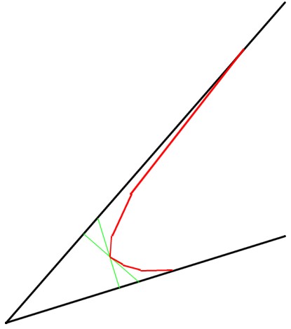
The explanation is not complicated. We begin with a sharp blade, use it until it is dull, then work through a process that will get the blade sharp again.
This is a scale drawing based on an actual test blade. The black outer line is a side profile of the sharpened blade before use. (For no particular reason the drawing shows the blade as it sits in the plane). Call this the sharp profile. The red line shows the profile after use. Metal has been worn away on both the top and the bottom of the blade. I call the resulting surfaces wear bevels. Call this the dull profile. This is an extreme close up. The upper red line is about 0.003 inches, the lower red line about 0.00061". (Measurements from photomicrographs.) All the metal between the sharp profile and dull profile was worn away through contact with the wood during planing.
 It is now time to sharpen. The last 0.003" of the back is no longer flat. Worse, you cannot make it flat by flattening the back again unless you remove 0.00027" of metal from the entire back. Not only would this take a very long time, it would reduce the thickness of the blade.
So, after the first use, the flatness of the back is no longer a factor in blade sharpness. All that time spent flattening the back (assuming you even flattened enough to remove any wear bevel at the edge) is no longer providing any benefit. All the effort the blade manufacturer put into flattening the back beyond this level of unevenness - 0.00027" - was wasted. The original back will never again make contact with the savings or the wood. The effort flattening the back no more helps the sharpness of tool than putting the tool in a fancy box or advertising it in a glossy magazine.
 What do you do now? Send it back? Lap it all over again? Not likely. If you want your originally flattened back to be one side of the sharpened edge you can grind (from the front) until you have ground past the back wear bevel. That means, you grind 0.003" of metal off the end of the blade. The upper blue line shows how much metal you must remove if you use this option. You must remove all the metal below that line.
This is too much metal to remove by honing from the front. Honing typically removes metal to a depth of less than 0.0003" over a small area. To remove all of the back wear bevel by honing from the front you would have to remove metal to a depth of 0.003" over a much greater area. So, honing is out. You must grind every time you sharpen and you must remove a lot of metal.
As an added complication, if you grind from the front you will be able to feel a burr as soon as you have removed about one quarter of the back wear bevel. You might think you have removed the back wear bevel, but you have only started to remove it. Not only do you have to grind every time, you will probably won't grind enough.
Finally, I believe that grinding through the edge is a mistake. In summary, grinding weakens the metal structure well below the bottom of the scratches you produce, especially with larger grit abrasives. So, not only does this approach waste far more of the blade than necessary, it degrades the steel at the edge, producing a less durable edge.
 The alternative is to start from the geometry of a worn blade and devise a sharpening protocol based on that. Since the back of the worn blade must have a wear bevel, the honing protocol takes that into account - by using back bevels. I hone from the front to just remove the front wear bevel, relying on honing back bevels to remove the back wear bevel. When the front microbevels get too wide, I grind from the front using a bench stone to almost remove the front microbevels - leaving all of the back wear bevels - then hone new microbevels, on the front and back.
The upper blue line here looks the same as the blue line in the flattening the entire back case. The back bevel is not the entire back - it is just about 0.01" at the edge. Honing this very narrow strip along the edge takes very little time. Honing back bevels add less than a minute to the total honing time.
So, reliance of a separate flattening step helps only once and does harm for the rest of the life of the blade.
To take this a little farther, plane blade advertising which stresses the flatness of the back - to a flatness tolerance of +-0.0002" or better over the working surface, and with an average roughness surface finish of 0.000005" or better - is a disservice to plane users.
Finally, advertising that stress the flatness of the back of plane blades indicates a fundamental misunderstanding of plane operation on the part of plane designers. By designing planes that require flat backs on plane irons, we get designs that do not work with real life blades. I am thinking here of low angle bevel up plans with bedding angle of 12 degrees. The plane works well when the plane iron back is flat - with a new blade. Thereafter, the plane does not work as well because people cannot sharpen the blade to this geometry. The result is an edge with too shallow a clearance angle to work well.
Planes and plane blades for which flat blades backs are important are probably useful only to people who buy tools in big box stores and don't use them enough to ever dull the blade. Essentially a disposable blade and plane.
The shape of a worn chisel could be much different from that of a worn plane blade. Chisels slice, plane blades scrape. Chisels are usually used with zero clearance angle, planes are never used with a zero clearance angle. This difference in use probably results in a different worn tool shape - a different ratio of front and back wear. I have no test that uses a chisel until it is dull, so have never photographed a chisel dulled through a repeatable process. I believe it is however safe to assume that there is wear on both sides of a chisel, suggesting that some attention must be paid to either adding a back bevel or removing the back wear bevel.
The problem with bench chisels, paring and mortise chisels, is that you often want to use the back as a jig -- you use the flat back to align the chisel during use.
When paring, you often lay the chisel flat on the back (bevel up) and push it forward. If there is a back bevel, the chisel will not cut a flat surface, but will ride up the back bevel. If you always pare with the bevel down rather than up, a back bevel should be no problem.
When mortising, especially at the mortise ends, you have to be able to cut straight down. If there is a back bevel, a chisel held vertically will not cut a 90 degree face. With more skill, a 3 degree tilt when you have a 3 degree back bevel, you could do it. In fact, with practice I expect you would soon discover the tilt you need to get your mortise chisel to do straight down, adjusting as the chisel works down through the wood. After all, you have to learn what 0 degrees feels like if you use no back bevel!
Carving chisels are a slightly different issue. Most are not flat, so there is no way to put on a back bevel with my jigs. In fact, since most are curved, any use of jigs is a problem. So, while back bevels are usually not an issue with carving chisels, front microbevels can be useful. In use, raising the handle can cause the edge to rotate around the back of the microbevel. Lifting the handle tilts the edge down for a deeper cut, lowering the handle raises the edge for a shallower cut. With practice, this allows very fine control.
Bottom line, you probably get a better edge but may need more practice to control the tool. I personally don't use back bevels on chisels.
Harrelson Stanley thinks he has with his Sharp Skate.
My early assessment of side-to-side [STS] honing versus front-and-back FAB honing concludes that even with a much better jig than the Sharp Skate, STS honing probably produces an inferior edge.
Many of these claims go against the conventional wisdom. Many contradict the claims of respected tool makers. Can any of them be right? Worse yet, can all of them be right?
Consider one example I just (Apr 2007) noticed. In some of my first plane blade tests (spring 2002) I discovered that A2 blades were only slightly more durable than high-carbon steel blades (but usually wore unevenly - see the blade tests). Lee Valley claimed in their 2001-2002 catalogue that "we found these A2 tool steel blades held a keen edge five times longer than both OEM blades and high-carbon steel replacement blades". In their May 2007 catalogue they say: "our A2 blades will hold an edge longer than most high-carbon steel blades". Quite a change of opinion, especially since the earlier opinion was based on their own testing. I still think that A2 blades last a little longer than any O1. However, you have to use larger included angles which may adversely affect the quality of the planed surface.
In the book Hand Tool Essentials from Popular Woodworking, David Charlesworth says that "an A2 cryogenically treated ... will enable you to work about four times longer than a carbon steel blade." David should publish his test methodology since it disagrees with the results that I, and others, have obtained.
All of my opinions are backed by test data, and usually by photomicrographs taken during the test. None rely on unreported tests or conventional wisdom. None are based on commercial interests.
So, you can disregard my claims for variety of reasons, but not because they are wrong. In particular, you can continue honing without a jig on your favourite piece of stone and continue to think you are getting great edges. In fact, you are not. All irons honed without a jig have inferior edges. All plane irons honed without a back bevel have inferior edges.
Set aside your scepticism. Take a little time. Make the jig. Buy the abrasive sheets. Make the sharpening station. Try it out. Make the bench stone vice. Try hand grinding primaries. Send me an email if you have any problems, questions, or contributions!
I believe all of the above claims will be conventional wisdom in a few years. Back to the top.
Previous page of the FAQ - Grinding wheels
Next page of the FAQ - Miscellaneous
Return to the Sharpening page.
Return to the Sharpening and testing home page.
Lost? Try looking around the site map. You can also reach the site map from the little map at the top of each page.
Questions? Comments?
You can email me here.
Back to the top.